Blog


How to Install an ESD Workstation

April 21, 2014

How to install an ESD Workstation:mt4500b-mat-kit

  1. Lay the table mat flat on the workbench with the snaps toward the operator. (Tip: Mild heat (sun light) will remove creases caused by shipping.)
  2. Connect the common point ground cord to the table mat by snapping it to the left or right snap.CP2500
  3. Connect the coil cord to the common point ground cord by plugging the banana plug into one of the ground cord’s banana jacks.
  4. Snap the wrist band to the coil cord. (Tip: make sure that the operator wears the wrist band on bare skin and tightens the band so that no gap exists between the skin and the band.
  5. Lay the floor mat on the floor in front of the workbench with the snaps toward the bench.
  6. Connect the floor mat ground cord to one snap on the floor mat.WB4037
  7. Connect the common point ground cord and floor mat ground cord to ground. Use the green wire building ground point as specified in EOS/ESD Standard 6. Connection to this ground point is most easily accomplished by removing the center AC outlet plate cover screw, placing the screw through the eyelets from both ground cords, and replacing the screw. The wires can be moved to the left and right sides of the screw so that they do not obstruct the outlet.
  8. comfort-dome-esd-mat-ground-cordHeel Grounders: Open the velcro strap. Place foot back into shoe and slip rubber cup onto the heel of the shoe. Insert tab into shoe and trim excess tab material with scissors if necessary.  Close velcro strap. Repeat procedure for other shoe.

Newly installed workstations should be tested for continuity. A surface resistivity meter with a “resistance to ground” function can be used to test continuity from the ground point to all parts of the workstation.


New Product Announcement: Comfort Dome ESD Anti-Fatigue Mat

March 19, 2014

Transforming Technologies is proud to announce the addition of the Comfort Dome ESD Anti-Fatigue Mat to our line of ESD Products.

The Comfort Dome ESD Anti-fatigue matting is offers unmatched operator comfort.

The Comfort Dome ESD Anti-fatigue matting is offers unmatched operator comfort.

Transforming Technologies Comfort Dome ESD Anti-Fatigue is a 100% rubber molded mat that provides unparalleled comfort in areas where static control is a concern. Evenly spaced domes on the surface of the mat provides superior anti-fatigue relief and slip resistance. These mats are available in single work-area mats sized 2’x3′ and 3’x4′ or in 3’x4′ interlocking sections for long assembly lines.

The Comfort Dome ESD Anti-Fatigue Mat meets or exceeds requirements of ANSI ESD-S20.20 and the recommendations of ESD 4.1.

For price and availability on the Comfort Dome series mats or for information on any products in Transforming Technologies full line of ESD products, please call 419-841-9552 or email info@transforming-technologies.com.


New Product Announcement: CC2695P Series Dual Wire Coil Cord with Parking Jack

February 3, 2014

Transforming Technologies is proud to announce the addition of the CC2695P Series Dual Wire Coil Cord with Parking Jack to our line of ESD Products.CC2695P Coil Cord with Parking Jack

The CC2695-P’s polyurethane coil insulation and strain relief molding offers excellent coil memory and endurance. The molded snap head provides a convenient parking jack for the cord with not in use. Two female snaps, a 3.5mm phono plug and 1 meg resister are standard. Dual blue and black 4 mm sockets help maintain a constant connection and dual wire wrist straps provide redundancy. When used with resistive loop (dual wire) monitors, the CC2695P wrist strap sets continuously verify resistance to ground. Available in 5′, 10′, and 20′ feet lengths.

For price and availability on the CC2695-P series coil cords or for information on any products in Transforming Technologies full line of ESD products, please call 419-841-9552 or email info@transforming-technologies.com.


Resistance Measurement Meter for Conveyor Belt

January 30, 2014

ESD-Q&A

This week’s ESD Q&A question comes from StaticCare reader Tim, he asks:

Question: What type of instrument should I use to measure the resistance on our conveyor belt?

Answer:

Conveyor Belt

Hello Tim,

Thank you for taking the time to submit your question to Transforming Technologies.

You will want to use a surface resistance meter with a 2.27 Kg (5lb) electrode, such as the SRM500K, for the measurement. For a flat belt conveyor, you can put the electrode on the conveyor belt and measure the resistance to equipment ground. For an edge belt conveyor, place a metal plate on the conveyor and measure the resistance from the plate to equipment ground. You may want to isolate one side of the plate from the belt to make sure that each belt is grounded.

Transforming Technologies will answer questions concerning all things ESD: static causes, threats,  ESD prevention, best practices and all things static in a feature we call ESD Q&A.  If you have ESD questions that you would like to be answered, email info@transforming-technologies.com  with Q&A in the subject line.


Auditing an ESD Worksurface

January 16, 2014


ESD-Q&A


This week’s ESD Q&A question comes from StaticCare reader Paul, he asks:

Question: What measurement or measurements do I need to make when auditing an ESD worksurface?

Answer:

Hello Paul,

Thank you for taking the time to submit your question to Transforming Technologies.

There are three primary measurements for evaluating a work surface; Resistance Point to Point (RTT – also known as Resistance Top to Top), Resistance to Groundable Point (RTGP) and Resistance to Ground (RTG).

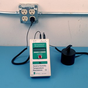
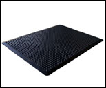
Figure 1 – Resistance To Ground (RTG)

Resistance to Ground Measurement

For general auditing purposes, the primary measurement is RTG. This measurement is made using a 5 lb electrode connected to the positive terminal of the resistance meter. The electrode is placed on the work surface in the most heavily used area. The negative lead is connected to electrical ground. This measurement assures that the mat is connected to AC Equipment Ground. ESD standard procedure says to test at 10 volts, and if the measurement exceeds 1.0 x 10⁶ ohms, switch to 100 volts. If you are certain that your worksurface material has a resistance greater than 1.0 x 10⁶ ohms, you may want to start at 100 volts to save time.

A simple and safe way to connect to AC Ground is by using a grounding plug, such as the Transforming Technologies AD22. The AD22 assures a solid connection to the third wire ground of an AC outlet, while insulating the plug from the hot and neutral wires. Always check electrical outlets for proper wiring before using grounding plugs.

If the resulting RTG measurement is within your required limits, no further work surface testing is required and you can proceed to the next work surface. Should the RTG measurement exceed your limits, clean the work surface with an approved cleaning product, check all wiring connections to make sure that they are secure and re-test. Should the measurements still exceed your limits you will then want to conduct a Resistance to Groundable Point (RTGP) measurement.

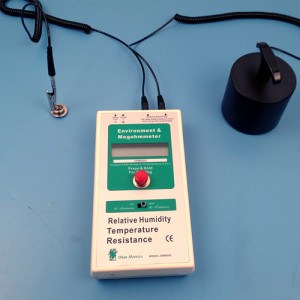
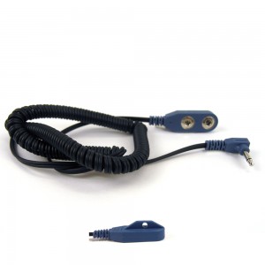
Figure 2 – Resistance Point To Groundable Point (RTGP)

Resistance to Groundable Point Measurement

This measurement is similar to the RTG measurement except that the negative lead is attached to the grounding point (snap) of the work surface. The testing is performed using 100 volts when the expected resistance is greater than 1.0 x 10⁶ ohms.

Should this measurement provide a reading that is within your requirements the problem is somewhere between the snap and AC Ground. Typically, either the ground wire became disconnected or it is faulty. Check and verify all wiring between the work surface and the AC equipment ground.

If this measurement also provides a value that exceeds your requirements, then there may be a problem with the work surface. A point-to-point resistance measurement can be done to verify the performance of the work surface material.

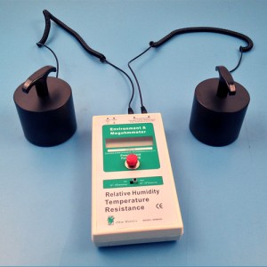
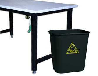
Figure 3 – Resistance Point To Point (RTT)

RTT – Resistance Point-to-Point

This measurement is made using two 5 lb electrodes. The electrodes are placed 10” apart on the work surface in various locations. Figure 3 is an example of a point-to-point test.

The testing is performed using 100 volts when the expected resistance is greater than 1.0 x 10⁶ ohms.

If the reading meets your requirements, there is possibly a connection problem with the groundable point. Should the reading exceed your limits the work surface is likely faulty and should be replaced.

It is important that RTG measurements be made regularly. The frequency of testing is dependent up on internal requirements and testing history. RTG testing must be performed even if constant monitoring is in place, as constant monitors verify ground connection of the worksurface, but not the performance of the worksuface.


The Cause for ESD Wastebaskets

December 4, 2013


ESD-Q&A


This week’s ESD Q&A question comes from StaticCare reader Stephanie, she asks:

Question: Is there really a need for an ESD wastebasket?

Answer:

Hello Stephanie,

Thank you for taking the time to submit your question to Transforming Technologies.

It is fair to wonder why there is a need for ESD wastebaskets. If the basket resides underneath a workstation and stays there permanently, the need may not exist. It is extremely unlikely that a wastebasket that stays underneath a workstation could present a danger to ESD sensitive devices, regardless of the field voltage that may exist on the basket.

There are a number of circumstances however, when the wastebasket could present a significant hazard to electronic products. The following are just a few examples of potentially risky scenarios:

Work surface cleaning:   The operator lifts the wastebasket to the edge of the work station to collect the debris being removed. Should product be present on the work surface and not contained in a shielding container, there is a good opportunity for exposure to electrostatic fields that exceed safe limits.

Lead trimming/board cleaning operations:   When trimming component leads or using aerosol cleaners on PCBs (Printed Circuit Boards), some operators will hold the PCB over the wastebasket to catch the clippings or solvent run-off. Many times the PCB will be placed well into the waste container to assure catching the unwanted materials. This operation puts PCBs and ESD sensitive devices very close to potentially significant electrostatic fields.

Aisle proximity:  Some wastebaskets have been observed in close proximity to production floor aisles where product transfer carts pass or may be parked. ANSI/ESD S2020 requires items that generate 2000 volts or more (measured at 1” from the item) be kept at least 12” from ESD sensitive devices. Using ESD wastebaskets eliminates the risk of carts being parked next to static generating baskets.

While company ESD policies may prohibit some of the actions mentioned above, it does not mean that they will not occur from time to time. ESD wastebaskets provided assurance that the wastebasket will never be an ESD threat to your product.

Transforming Technologies offers ESD wastebaskets in static dissipative polypropylene and in stainless steel for clean room operations. If a liner is to be used for easier maintenance, Transforming Technologies offers them in both conductive and static dissipative.

WBAS28 ESD Wastebasket


WBAS 28

  • Volume: 28 Quart (7 gallon)
  • Height: 15″, Opening: 10.5″ X 14.75″
  • Carbon Loaded


New Product Announcement: HG9000 Series Non-Marking D-Ring/Elastic Sole Grounder

October 10, 2013

Transforming Technologies is proud to announce the addition of the HG9000 Series ESD Non-Marking D-Ring/Elastic Sole Grounders to our line of ESD Products.

HG9000-sole-grounder-series

Sole Grounders, or Foot Grounders, cover more of the shoe which allows more contact to the ESD floor during the process of a step.

The HG9000 series non-marking D-ring/elastic sole grounder provides a more complete path to ground than regular heel or toe grounders due to a wider and more consistent contact area. The HG9000 series will not mar shoes or floors – reducing maintenance costs of touching up on floors. Available in XS, S, M and L sizes.

ESD Sole Grounders (or ESD Foot Grounders) have over 20 times the surface contact of standard esd heel straps. This surface area advantage extends the life of the Sole grounder over standard heel grounders which fail over time due to even the slightest contamination, necessitating replacement or cleaning, wasting time, and costing money.

These sole grounders provide rapid and complete static dissipation due to constant contact through entire walking motion. Wearing the conductive ribbon inside the shoe or sock assures proper electrical contact with the user. A rugged 1 meg ohm buried resistor is standard. Heel grounders are worn on both feet to provide consistent grounding while in motion.

 Features

  • Non-Marking
  • Buried Resistor
  • Full Sole Coverage Design

For price and availability on the HG9000 series soles grounders or for information on any products in Transforming Technologies full line of ESD products, please call 419-841-9552 or email info@transforming-technologies.com.


ESD Wrist Strap Testing and Monitoring

September 19, 2013

One of the requirements of any quality ESD control program is to minimize the charge (also called voltage) on operators. When operators are charged, they can transfer this charge to the product, possibly causing damage or destruction. One effective way to reduce static charging on people is to ground them through the use of a wrist strap and coil cord. When working properly, the wrist strap system (band and coil cord connected to common point ground) can control voltages on people down to 10 volts and less and limit damage.

While wrist strap systems are the most common and effective way to minimize voltage on personnel, they are also the ESD control element that is most likely to eventually fail over time. A broken wire in the coil cord, a dirty cuff interior, incorrect wearing of the strap (too loose or placed over clothing), and high skin resistance are just a few of many causes of wrist strap failure. Should any of the previous examples occur, the resistance between the operator and ground increases, and subsequently, so does voltage. Therefore, it is imperative that measures are taken to assure that the operator is properly grounded when wearing a wrist strap.

combination-esd-tester-pdt800-lg

The PDT800 is a deluxe “Near-Fail” wrist strap and foot wear combination tester with a digital read out, “near-fail” LED indicator, human body noise filtration, and options to test wrist strap only, foot only, or both wrist and feet.

ESD Test Stations

One way to assure that the wrist strap system is working correctly is for the operator to use a test station. The test station assesses the resistance of the wrist strap system, including the operator, and provides a pass/fail indication. Some more advanced test stations will also provide the actual resistance measurement and may even indicate that the system is nearing the failure level. Many companies institute this type of testing system. Some companies require testing just once at the beginning of the shift. Other companies may require re-testing when the operator leaves for break, and some companies have systems that require the operator to test and pass the wrist strap system before they are allowed to enter the ESD Protected Area (EPA). Regardless of how many times an operator tests, there is a risk that at some point while handling ESD sensitive devices or assemblies, the wrist strap system will fail.

Transforming Technologies offers several testing station options that range from wrist strap monitors (WST200), wrist strap and footwear test stations (GTS600K), wrist strap and individual foot test stations (GTS900K), test stations with “near-fail” technology (PDT700K), and test stations with “near-fail” technology and digital display (PDT800K). These testing stations function with a standard wrist strap and coil cord using a banana jack connector and standard heel grounders.

Constant Monitoring

cm410-rubber-wrist-strap

The CM410 continuously monitors any one standard wrist strap and bench, is easy to use, and easy to install.

If a wrist strap fails the test at the beginning of a shift, the question arises, “When did the failure take place and how much product was handled after the failure?” Constant monitors provide assurance that the wrist strap system is working and alarms immediately if there is any disconnect from the operator to ground. There are several benefits to constant monitor systems:

  • They provide immediate notification of a problem and alert the operator to not handle the product until the problem is resolved
  • They monitor the wrist strap at the work location, eliminating the possibility of a functional wrist strap but a defective ground attachment
  • They eliminate the need for recording and storing test results
  • Some units will also monitor the work surface to verify that it is still connected to ground

Transforming Technologies offers several constant monitor options that range from monitoring a single operator (CM400), an operator and a work surface (CM410), and two operators and a single work surface (CM420). These monitors function with a standard wrist strap and coil cord using a banana jack connector.

Wrist straps are the primary method for removing charge from operators handling ESD sensitive products. Constant monitors provide assurance that the system is working as designed and the products are being handled safely.


2013 EOS & ESD Symposium & Exhibits

August 29, 2013

Stop by the Transforming Technologies booth at the 2013 ESD Symposium at the Rio All Suites in Las Vegas,

rio-all-suites-esd-symposium

Rio All Suites Hotel in Las Vegas, Nevada

Nevada! The EOS & ESD Symposium runs from Sunday, September 8th through Friday, September 13th. During the Exhibit on September 9th-11th, we will be located at booth 111. Feel free to drop in and ask us any questions you may have about ESD or any of our products.

The exhibit hours are:
Monday, September 9: 6:00 p.m. – 9:00 p.m.
Tuesday, September 10: 9:30 a.m. – 5:30 p.m.
Wednesday, September 11: 9:30 a.m. – 1:00 p.m.


2012 EOS & ESD Symposium

2012 EOS & ESD Symposium

John G. Kappenman of Storm Analysis Consultants will be the Keynote speaker for the event, and he will be speaking on Geomagnetic Superstorm Events and their impacts on power grids. More information about the schedule for the event seminars, tutorials, technical sessions, workshops, and showcases can be found here.

Visit the ESDA website for information on purchasing Symposium and Tutorial passes, airfare, hotel, and meals. Their bundle form is located here.

They also have the 2013 EOS & ESD Symposium Program on their website. This program contains descriptions for each of the sessions that will be offered.


Measuring ESD Mat Resistance: 10 volts vs. 100 volts

July 11, 2013

ESD-Q&A


This week’s ESD Q&A question comes from StaticCare reader John, he asks:

Question: When measuring ESD Mat resistance, I have noticed that the resistance measures higher on some of my older ESD rubber mats when using 10V and will sometimes be greater than 10^9 ohms. Switching to 100V will lower the resistance into the green, passable range(less than 10^9 ohms). If the mat passes at 100V, is that sufficient to give the mat a pass? When should I use 10 volts vs. 100 volts?

Answer:

Hello John,

Thank you for submitting your question to Transforming Technologies.

Industry standards specify the test voltage required when testing or verifying ESD control items (i.e. mats).    For verification of mats, or work surfaces, you can reference the ESD Association TR53 Compliance Verification document.  This is a free download at www.esda.org.   (select the Standards tab and scroll down to TR53).

The following rule applies for resistance testing of ESD control items:

Perform the test at 10 volts.   If the resistance is < 1.0 x 10⁶ ohms record the reading.

If the measurement at 10 volts is ≥1.0 x 10⁶ ohms, switch to 100 volts, make your measurement and record the result.

Most ESD mat materials are designed to have a resistance greater than 1.0 x 10⁶ ohms, so you can start your testing at 100 volts.  In the example that you stated, the mat that you tested meets the requirements.  If you are seeing the values creep higher it would be wise to test the older mats more frequently to verify that they are still under 1.0 x 10⁹ ohms.

Every Thursday, Transforming Technologies will answer questions concerning all things ESD: static causes, threats,  ESD prevention, best practices and all things static in a feature we call ESD Q&A.  If you have ESD questions that you would like to be answered, email info@transforming-technologies.com  with Q&A in the subject line.

Translate »